What does the p wave reflect on the ECG - deciphering the data obtained, the reasons for the bifurcation of the wave
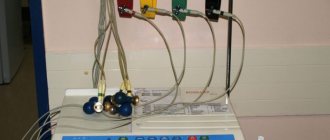
After examination by a cardiologist, the examination begins with electrocardiography. This procedure is very informative, despite the fact that it is carried out quickly and does not require special training or additional costs.
An electrocardiogram is always taken upon admission to the hospital.
The cardiograph records the passage of electrical impulses through the heart, records the heart rate and can detect the development of serious pathologies. The waves on an ECG give a detailed picture of the different parts of the myocardium and how they work.
https://www..com/watch?v=channelUCd2IZeS9s_HfmLjzVt8XM9Qvideos
The norm for an ECG is that different waves differ in different leads. They are calculated by determining the value relative to the projection of the EMF vectors onto the lead axis.
The tooth can be positive or negative. If it is located above the cardiography isoline, it is considered positive, if below it is considered negative.
A biphasic wave is recorded when, at the moment of excitation, the wave passes from one phase to another.
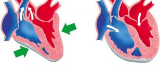
The conduction system of the heart is a complex structure. It consists of:
- sinoatrial node;
- atrioventricular;
- bundle branches;
- Purkinje fibers.
The sinus node, as a pacemaker, is a source of impulses. They are formed at a rate of 60-80 times per minute. With various disorders and arrhythmias, impulses may be created more often or less frequently than normal.
Sometimes bradycardia (slow heartbeat) develops due to the fact that another part of the heart takes over the function of the pacemaker. Arrhythmic manifestations can also be caused by blockades in various zones. Because of this, the automatic control of the heart is disrupted.
Normal electrocardiogram
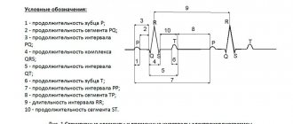
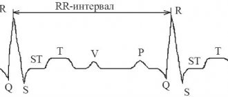
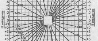
Any ECG consists of several waves, segments and intervals, reflecting the complex process of propagation of an excitation wave throughout the heart.
The shape of electrocardiographic complexes and the size of the teeth are different in different leads and are determined by the size and direction of the projection of the moment vectors of the cardiac EMF onto the axis of a particular lead. If the projection of the torque vector is directed towards the positive electrode of a given lead, an upward deviation from the isoline is recorded on the ECG - positive waves.
If the projection of the vector is directed towards the negative electrode, a deviation downward from the isoline is recorded on the ECG - negative waves.
In the case when the moment vector is perpendicular to the lead axis, its projection onto this axis is zero and no deviations from the isoline are recorded on the ECG.
If during the excitation cycle the vector changes its direction relative to the poles of the lead axis, then the wave becomes biphasic.
The general scheme for decoding the ECG is presented below.
What does an ECG show?
If you know the norms for cardiogram indicators, how the teeth should be located in a healthy person, you can diagnose many pathologies. This examination is carried out in a hospital setting, on an outpatient basis and in emergency critical cases by emergency doctors to make a preliminary diagnosis.
Changes reflected in the cardiogram may show the following conditions:
- rhythm and heart rate;
- myocardial infarction;
- blockade of the cardiac conduction system;
- disruption of the metabolism of important microelements;
- blockages of large arteries.
Obviously, research using an electrocardiogram can be very informative. But what do the results of the data obtained consist of?
Detailed interpretation of the electrocardiogram
The norm for the P wave is located above the isoline. This atrial wave can be negative only in leads 3, aVL and 5. In leads 1 and 2 it reaches its maximum amplitude. The absence of a P wave may indicate serious disturbances in the conduction of impulses through the right and left atrium. This tooth reflects the state of this particular part of the heart.
The P wave is deciphered first, since it is in it that the electrical impulse is generated and transmitted to the rest of the heart.
https://www..com/watch?v=ytdevru
Splitting of the P wave, when two peaks are formed, indicates an enlargement of the left atrium. Often bifurcation develops with pathologies of the bicuspid valve. A double-humped P wave becomes an indication for additional cardiac examinations.
The PQ interval shows how the impulse passes to the ventricles through the atrioventricular node. The norm for this section is a horizontal line, since there are no delays due to good conductivity.
The Q wave is normally narrow, its width is no more than 0.04 s. in all leads, and the amplitude is less than a quarter of the R wave. If the Q wave is too deep, this is one of the possible signs of a heart attack, but the indicator itself is assessed only in conjunction with others.
The R wave is ventricular, so it is the highest. The walls of the organ in this zone are the densest. As a result, the electric wave travels the longest. Sometimes it is preceded by a small negative Q wave.
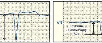
During normal heart function, the highest R wave is recorded in the left precordial leads (V5 and 6). However, it should not exceed 2.6 mV. A tooth that is too high is a sign of left ventricular hypertrophy.
This condition requires in-depth diagnostics to determine the causes of the increase (ischemic heart disease, arterial hypertension, heart valve defects, cardiomyopathies).
If the R wave decreases sharply from V5 to V6, this may be a sign of MI.
After this reduction, the recovery phase begins. This is illustrated on the ECG as the formation of a negative S wave.
After the small T wave comes the ST segment, which should normally be represented by a straight line.
The Tckb line remains straight, there are no bent areas on it, the condition is considered normal and indicates that the myocardium is completely ready for the next RR cycle - from contraction to contraction.
Electrocardiogram analysis
a - induction currents - network induction in the form of regular oscillations with a frequency of 50 Hz;
b — “swimming” (drift) of the isoline as a result of poor contact of the electrode with the skin;
c — interference caused by muscle tremor (irregular frequent vibrations are visible).
Interference occurring during ECG recording
Secondly, it is necessary to check the amplitude of the control millivolt, which should correspond to 10mm.
Thirdly, the speed of paper movement during ECG recording should be assessed. When recording an ECG at a speed of 50 mm, 1 mm on paper tape corresponds to a time period of 0.02 s, 5 mm - 0.1 s, 10 mm - 0.2 s, 50 mm - 1.0 s.
Possible errors in research
It is possible to obtain unreliable data from an electrocardiogram if the following factors influence the cardiograph when recording signals:
- alternating current frequency fluctuations;
- displacement of the electrodes due to their loose application;
- muscle tremors in the patient's body.
All these points affect the obtaining of reliable data when conducting electrocardiography. If the ECG shows that these factors have taken place, the study is repeated.
Timely consultation with a doctor will help diagnose pathologies in the early stages
https://www..com/watch?v=ytcopyrightru
When an experienced cardiologist interprets a cardiogram, a lot of valuable information can be obtained. In order not to trigger the pathology, it is important to consult a doctor when the first painful symptoms occur. This way you can save your health and life!
Source: https://sanatory-duna-anapa.ru/razdvoenie-zubtsa-r-na-ekg/
Why is an electrocardiogram performed?
After examination by a cardiologist, the examination begins with electrocardiography. This procedure is very informative, despite the fact that it is carried out quickly and does not require special training or additional costs.
The cardiograph records the passage of electrical impulses through the heart, records the heart rate and can detect the development of serious pathologies. The waves on an ECG give a detailed picture of the different parts of the myocardium and how they work.
The norm for an ECG is that different waves differ in different leads. They are calculated by determining the value relative to the projection of the EMF vectors onto the lead axis. The tooth can be positive and negative. If it is located above the cardiography isoline, it is considered positive, if below it is considered negative.
A biphasic wave is recorded when, at the moment of excitation, the wave passes from one phase to another.
Important! An electrocardiogram of the heart shows the state of the conduction system, consisting of bundles of fibers through which impulses pass.
By observing the rhythm of contractions and the characteristics of rhythm disturbances, one can see various pathologies.
The conduction system of the heart is a complex structure. It consists of:
- sinoatrial node,
- atrioventricular,
- bundle branches,
- Purkinje fibers.
The sinus node, as a pacemaker, is a source of impulses. They are formed at a rate of 60-80 times per minute. With various disorders and arrhythmias, impulses may be created more often or less frequently than normal.
Sometimes bradycardia (slow heartbeat) develops due to the fact that another part of the heart takes over the function of the pacemaker. Arrhythmic manifestations can also be caused by blockades in various zones. Because of this, the automatic control of the heart is disrupted.
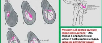
Determination of the heart axis
Another step in deciphering the electrocardiogram is determining the axis of the heart. A normal tilt is considered to be between 30 and 69 degrees. Smaller indicators indicate a deviation to the left, and larger indicators indicate a deviation to the right.
| In healthy people of people , more often in young people and especially in children, on the ECG in the right precordial leads (V1, V3R, V2) a second r wave (denoted r) of small amplitude and width is often observed - type rSrvl or splitting on the ascending knee of the SV1 wave. This small tooth is associated with the excitation of the “supraventricular ridge”, which is still hypertrophied in the fetus, located in the region of the conus pulmonale of the right ventricle. This area is the last to be excited, so its hypertrophy causes an increase in EMF at the end of the QRS period. Scallop hypertrophy develops in the fetus and is not associated with hemodynamic pathology after birth. In this regard, people with a hypertrophied “supraventricular crest” should be considered healthy. Presence of a small tooth r'v1 , which is usually of smaller amplitude than the rvl wave or equal to it, in the absence of its widening, widened SV6, QRS widening and other ECG changes characteristic of incomplete right bundle branch block, should be regarded as a variant of a normal ECG. We believe that the signs of “supraventricular crest syndrome” should be indicated in the first, descriptive part of the ECG protocol. If the specialist analyzing the ECG If I am convinced that these signs are not associated with hypertrophy of the right ventricle or “incomplete” (“partial”) blockade of the right branch of the His bundle (see the corresponding chapters), then this syndrome should not be mentioned in conclusion, since it is not associated with pathology. ECG healthy man K., 27 years old. The sinus rhythm is regular, 63 per minute. Interval P - Q = 0.17 sec. P=0.08 sec. QRS=0.08 sec. Q - T=0.36 sec. RII>RIII>RI. AQRS=+80°. At=+49°. Angle QRS—T=31°. AR=+43°. The PI,II,V2-V6 wave is positive. PIII,V1 two-phase (+-) with a main positive phase. QRSIII complex type qR. QRSII,V4V6 type qRS. QRSV1 complex, rS type with pronounced cleavage on the ascending limb of the S wave. The cleavage tooth reaches the level of the isoelectric line. The T wave and RS-T segment are normal in all leads. Conclusion . Variant of a normal ECG. Vertical position of the electrical axis of the heart. Presented ECGs do not exhaust the entire set of options for a normal ECG, but are the main ones. The demonstrated analysis of these ECGs will allow the physician to understand other variations of a normal ECG. |
ECG interpretation
An electrocardiogram reflects only electrical processes in the myocardium: depolarization (excitation) and repolarization (restoration) of myocardial cells.
Correlation of ECG intervals with the phases of the cardiac cycle (ventricular systole and diastole).
Normally, depolarization leads to contraction of the muscle cell, and repolarization leads to relaxation.
To simplify further, instead of “depolarization-repolarization” I will sometimes use “contraction-relaxation”, although this is not entirely accurate: there is the concept of “electromechanical dissociation”, in which depolarization and repolarization of the myocardium do not lead to its visible contraction and relaxation.
Elements of a normal ECG
Before moving on to deciphering the ECG, you need to understand what elements it consists of.
Waves and intervals on the ECG.
It is curious that abroad the PQ interval is usually called PR.
Any ECG consists of waves, segments and intervals.
Teeth are convex and concave areas on the electrocardiogram. The following waves are distinguished on the ECG:
- P (atrial contraction),
- Q, R, S (all 3 teeth characterize ventricular contraction),
- T (ventricular relaxation),
- U (non-permanent wave, rarely recorded).
SEGMENTS A segment on an ECG is a segment of a straight line (isoline) between two adjacent teeth. The PQ and ST segments are of greatest importance. For example, the PQ segment is formed due to a delay in the conduction of excitation in the atrioventricular (AV) node.
INTERVALS An interval consists of a tooth (a complex of teeth) and a segment. Thus, interval = tooth + segment. The most important are the PQ and QT intervals.
Waves, segments and intervals on the ECG.
Pay attention to large and small cells (more about them below).
QRS complex waves
Since the ventricular myocardium is more massive than the atrial myocardium and has not only walls, but also a massive interventricular septum, the spread of excitation in it is characterized by the appearance of a complex QRS complex on the ECG.
How to correctly identify the teeth in it?
First of all, the amplitude (size) of individual waves of the QRS complex is assessed. If the amplitude exceeds 5 mm, the tooth is designated by a capital (capital) letter Q, R or S; if the amplitude is less than 5 mm, then lowercase (small): q, r or s.
The R wave (r) is any positive (upward) wave that is part of the QRS complex. If there are several teeth, subsequent teeth are indicated by strokes: R, R', R”, etc.
The negative (downward) wave of the QRS complex, located before the R wave, is designated as Q (q), and after - as S (s). If there are no positive waves at all in the QRS complex, then the ventricular complex is designated as QS.
Variants of the QRS complex.
Fine:
the Q wave reflects depolarization of the interventricular septum (the interventricular septum is excited)
R wave - depolarization of the bulk of the ventricular myocardium (the apex of the heart and adjacent areas are excited)
S wave - depolarization of the basal (i.e. near the atria) parts of the interventricular septum (the base of the heart is excited)
The RV1, V2 wave reflects the excitation of the interventricular septum,
and RV4, V5, V6 - excitation of the muscles of the left and right ventricles.
Necrosis of areas of the myocardium (for example, during myocardial infarction) causes expansion and deepening of the Q , so close attention is always paid to this wave.
ECG analysis
General scheme of ECG decoding
- Checking the correctness of ECG registration.
- Heart rate and conduction analysis:
- assessment of heart rate regularity,
- heart rate (HR) counting,
- determination of the source of excitation,
- conductivity assessment.
- Determination of the electrical axis of the heart.
- Analysis of the atrial P wave and P–Q interval.
- Analysis of the ventricular QRST complex:
- QRS complex analysis,
- analysis of the RS – T segment,
- T wave analysis,
- Q-T interval analysis.
- Electrocardiographic report.
Normal electrocardiogram.
1) Checking the correctness of ECG registration
At the beginning of each ECG tape there must be a calibration signal - the so-called control millivolt. To do this, a standard voltage of 1 millivolt is applied at the beginning of the recording, which should display a deviation of 10 mm on the tape. Without a calibration signal, the ECG recording is considered incorrect.
Normally, in at least one of the standard or enhanced limb leads, the amplitude should exceed 5 mm, and in the chest leads - 8 mm. If the amplitude is lower, this is called reduced ECG voltage, which occurs in some pathological conditions.
2) Heart rate and conduction analysis:
- assessment of heart rate regularity
Rhythm regularity is assessed by RR intervals. If the teeth are at an equal distance from each other, the rhythm is called regular, or correct. The spread of the duration of individual RR intervals is allowed no more than ± 10% of their average duration. If the rhythm is sinus, it is usually regular.
- heart rate (HR) counting
The ECG film has large squares printed on it, each of which contains 25 small squares (5 vertical x 5 horizontal).
To quickly calculate heart rate with the correct rhythm, count the number of large squares between two adjacent R-R waves.
At a belt speed of 50 mm/s: HR = 600 / (number of large squares). At a belt speed of 25 mm/s: HR = 300 / (number of large squares).
At a speed of 25 mm/s, each small cell is equal to 0.04 s,
and at a speed of 50 mm/s - 0.02 s.
This is used to determine the duration of the teeth and intervals.
If the rhythm is abnormal, the maximum and minimum heart rate is usually calculated according to the duration of the shortest and longest RR interval, respectively.
- determination of the excitation source
In other words, they are looking for where the pacemaker is located, which causes contractions of the atria and ventricles.
Sometimes this is one of the most difficult stages, because various disorders of excitability and conduction can be very confusingly combined, which can lead to incorrect diagnosis and incorrect treatment.
To correctly determine the source of excitation on an ECG, you need to have a good knowledge of the conduction system of the heart.
SINUS rhythm (this is a normal rhythm, and all other rhythms are pathological). The source of excitation is located in the sinoatrial node.
Signs on the ECG:
- in standard lead II, the P waves are always positive and are located before each QRS complex,
P waves in the same lead have the same shape at all times.
P wave in sinus rhythm.
ATRIAL rhythm. If the source of excitation is located in the lower parts of the atria, then the excitation wave propagates to the atria from bottom to top (retrograde), therefore:
- in leads II and III the P waves are negative,
- There are P waves before each QRS complex.
P wave during atrial rhythm.
Rhythms from the AV connection. If the pacemaker is located in the atrioventricular (atrioventricular node) node, then the ventricles are excited as usual (from top to bottom), and the atria are excited retrogradely (i.e. from bottom to top).
At the same time, on the ECG:
- P waves may be absent because they are superimposed on normal QRS complexes,
- P waves can be negative, located after the QRS complex.
Rhythm from the AV junction, superimposition of the P wave on the QRS complex.
Rhythm from the AV junction, the P wave is located after the QRS complex.
Heart rate with a rhythm from the AV junction is less than sinus rhythm and is approximately 40-60 beats per minute.
Ventricular, or IDIOVENTRICULAR, rhythm
In this case, the source of rhythm is the ventricular conduction system.
Excitation spreads through the ventricles in the wrong way and is therefore slower. Features of idioventricular rhythm:
- QRS complexes are widened and deformed (they look “scary”). Normally, the duration of the QRS complex is 0.06-0.10 s, therefore, with this rhythm, the QRS exceeds 0.12 s.
- There is no pattern between QRS complexes and P waves because the AV junction does not release impulses from the ventricles, and the atria can be excited from the sinus node, as normal.
- Heart rate less than 40 beats per minute.
Idioventricular rhythm. The P wave is not associated with the QRS complex.
To properly account for conductivity, the recording speed is taken into account.
To assess conductivity, measure:
- the duration of the P wave (reflects the speed of impulse transmission through the atria), normally up to 0.1 s.
duration of the P – Q interval (reflects the speed of impulse conduction from the atria to the ventricular myocardium); interval P – Q = (wave P) + (segment P – Q). Normally 0.12-0.2 s.
Measuring the internal deviation interval.
3) Determination of the electrical axis of the heart.
4) Analysis of the atrial P wave.
- Normally, in leads I, II, aVF, V2 – V6, the P wave is always positive.
- In leads III, aVL, V1, the P wave can be positive or biphasic (part of the wave is positive, part is negative).
- In lead aVR, the P wave is always negative.
- Normally, the duration of the P wave does not exceed 0.1 s, and its amplitude is 1.5 – 2.5 mm.
Pathological deviations of the P wave:
- Pointed high P waves of normal duration in leads II, III, aVF are characteristic of hypertrophy of the right atrium, for example, with “cor pulmonale”.
- Split with 2 apexes, widened P wave in leads I, aVL, V5, V6 is characteristic of left atrium hypertrophy, for example, with mitral valve defects.
Formation of the P wave (P-pulmonale) with hypertrophy of the right atrium.
Formation of the P wave (P-mitrale) with left atrial hypertrophy.
4) PQ interval analysis:
normally 0.12-0.20 s.
An increase in this interval occurs when the conduction of impulses through the atrioventricular node is impaired (atrioventricular block, AV block).
There are 3 degrees of AV block:
- I degree - the PQ interval is increased, but each P wave corresponds to its own QRS complex (there is no loss of complexes).
- II degree – QRS complexes partially disappear, i.e. Not all P waves have their own QRS complex.
- III degree – complete blockade of conduction in the AV node. The atria and ventricles contract at their own rhythm, independently of each other. Those. idioventricular rhythm occurs.
5) Analysis of the ventricular QRST complex:
- analysis of the QRS complex.
- The maximum duration of the ventricular complex is 0.07-0.09 s (up to 0.10 s).
The duration increases with any bundle branch block.
- Normally, the Q wave can be recorded in all standard and enhanced limb leads, as well as in V4-V6.
- The amplitude of the Q wave normally does not exceed 1/4 of the height of the R wave, and the duration is 0.03 s.
- In lead aVR, there is normally a deep and wide Q wave and even a QS complex.
- The R wave, like the Q wave, can be recorded in all standard and enhanced limb leads.
- From V1 to V4, the amplitude increases (while the rV1 wave may be absent), and then decreases in V5 and V6.
- The S wave can have very different amplitudes, but usually no more than 20 mm.
- The S wave decreases from V1 to V4, and may even be absent in V5-V6.
- In lead V3 (or between V2 – V4), a “transition zone” is usually recorded (equality of the R and S waves).
- RS – T segment analysis
- The ST segment (RS-T) is the segment from the end of the QRS complex to the beginning of the T wave. – – The ST segment is especially carefully analyzed in case of coronary artery disease, since it reflects the lack of oxygen (ischemia) in the myocardium.
Normally, the ST segment is located in the limb leads on the isoline (± 0.5 mm).
- In leads V1-V3, the ST segment may shift upward (no more than 2 mm), and in leads V4-V6 - downward (no more than 0.5 mm).
- The transition point of the QRS complex to the ST segment is called point j (from the word junction - connection).
- The degree of deviation of point j from the isoline is used, for example, to diagnose myocardial ischemia.
- T wave analysis.
- The T wave reflects the process of repolarization of the ventricular myocardium.
In most leads where a high R is recorded, the T wave is also positive.
- Normally, the T wave is always positive in I, II, aVF, V2-V6, with TI> TIII, and TV6> TV1.
- In aVR the T wave is always negative.
- Q-T interval analysis.
- The QT interval is called electrical ventricular systole, because at this time all parts of the ventricles of the heart are excited.
Sometimes after the T wave a small U wave is recorded, which is formed due to short-term increased excitability of the ventricular myocardium after their repolarization.
6) Electrocardiographic report. Should include:
- Source of rhythm (sinus or not).
- Regularity of rhythm (correct or not). Usually sinus rhythm is normal, although respiratory arrhythmia is possible.
- Heart rate.
- Position of the electrical axis of the heart.
- Presence of 4 syndromes:
- rhythm disturbance
- conduction disturbance
- hypertrophy and/or overload of the ventricles and atria
- myocardial damage (ischemia, dystrophy, necrosis, scars)
ECG interference
Source: https://cardio-pad.ru/news/rasshifrovka-ekg/